The case: a 1.5 hp single-phase submersible pump rated 230 V, supplied from a 240 V panel. The cable runs 80 ft underground to the wellhead and 120 ft down the casing: 200 ft one-way. A pressure switch and the pump's control box are on the wall in the house.
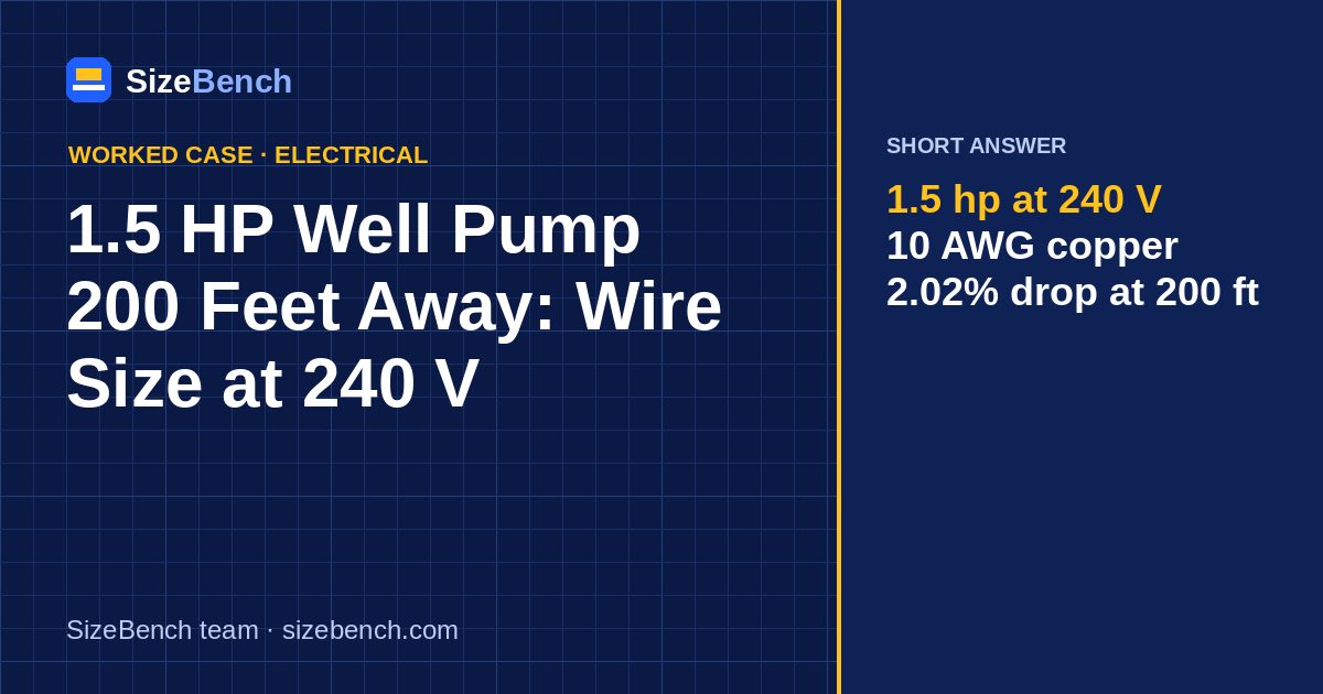
Short answer: 10 AWG copper for the whole 200 ft and a two-pole breaker of the size the control box or pump manual specifies, typically 20 A for this motor. The running drop is 2.02% at the NEC full-load current of 10 A. 12 AWG passes the pump makers' looser limit, but it costs more voltage at start-up, when a deep pump needs it most.

1. The current to design for
For motors, the NEC does not use the nameplate amps for wire sizing. It uses its own full-load current table. For a 1.5 hp single-phase motor at 230 V the table gives 10 A. Branch-circuit conductors for a single motor must be rated at least 125% of that:
10 A × 1.25 = 12.5 A
So ampacity alone would allow 14 AWG copper. Distance is what makes this case interesting. For the voltage-drop check we use two currents: the table's 10 A, and a submersible motor's service-factor amps, which are higher. We assume 11.5 A for this motor; read the real value on the pump's data plate or in the control box.
Power check: 1.5 hp × 0.7457 = 1.12 kW of shaft output. Electrical input is higher because the motor is not 100% efficient and has a power factor below 1, which is why 10 A × 240 V is more than the shaft power.
2. Running voltage drop at 200 feet
| Copper | Drop at 11.5 A (V) | Drop (%) | Voltage at the motor |
|---|---|---|---|
| 12 AWG | 8.9 V | 3.70% | 231.1 V |
| 10 AWG | 5.6 V | 2.32% | 234.4 V |
| 8 AWG | 3.5 V | 1.46% | 236.5 V |
Pump manufacturers publish maximum cable lengths per motor and wire size. Many of those charts allow a larger drop than the 3% we use here, which is why they often list 12 AWG as acceptable at this length. At 5% the calculator also picks 12 AWG (3.22%). Both answers can be "right"; the difference shows up at start-up.
3. Starting: the moment that matters
A submersible motor draws several times its running current for the fraction of a second it takes to start against a full column of water. We assume 5 × 10 A = 50 A at start (the motor's code letter gives the real figure). The voltage at the motor during that inrush:
With 12 AWG the motor sees about 16% less voltage at start; with 10 AWG about 10%. Lower starting voltage means lower starting torque and a longer start, which heats the motor and the start capacitor in the control box. On a well with frequent cycling, that is the difference between a pump that lasts and one that does not.
4. Distance table
Smallest copper that carries 12.5 A and meets the stated drop at 10 A, 240 V:
| One-way length | 3% target | Drop | 5% target | Drop |
|---|---|---|---|---|
| 100 ft | 14 AWG | 2.56% | 14 AWG | 2.56% |
| 150 ft | 12 AWG | 2.41% | 14 AWG | 3.84% |
| 200 ft | 10 AWG | 2.02% | 12 AWG | 3.22% |
| 250 ft | 10 AWG | 2.52% | 12 AWG | 4.02% |
| 300 ft | 8 AWG | 1.91% | 12 AWG | 4.83% |
| 400 ft | 8 AWG | 2.55% | 10 AWG | 4.03% |
Remember to count the whole path: panel to pressure switch, pressure switch to control box, box to wellhead, and wellhead down to the pump setting depth.

5. Why 240 V and not 120 V
The same 1.5 hp motor at 115 V has a table current of 20 A, twice as much. Current doubles and the voltage it is measured against halves, so the drop percentage is four times worse. At 200 ft and 3%, a 120 V version would need 4 AWG copper (2.05%). That is why deep-well pumps of this size are almost always 230 V.
6. Breaker and protection
- The breaker is a two-pole breaker; both hots must open together.
- For motor circuits, the NEC allows the short-circuit breaker to be well above the conductor's normal rating, up to 25 A for this motor, because overload protection is provided separately (in the motor or control box). Pump manufacturers usually specify a smaller value, and theirs is the one to use, typically 20 A at this size.
- 2-wire pumps have their starting components inside the motor; 3-wire pumps use a control box above ground. The 3-wire version needs three conductors plus ground down the well.
7. Cable types
- In the well: submersible pump cable, flat or round jacketed, listed for the purpose. Splice to the motor leads with a heat-shrink splice kit made for submersible use.
- Buried to the wellhead: UF-B cable or THWN-2 in conduit. Submersible pump cable is not a substitute unless it is also listed for direct burial.
- Ground: run an equipment grounding conductor all the way to the motor. A metal well casing must also be bonded to it.
8. Constant-pressure drives change the picture
More and more wells use a constant-pressure system: a variable-frequency drive on the wall that feeds a three-phase submersible motor and ramps it up gently. Two things change:
- No hard start. The drive soft-starts the motor, so the start-up voltage dip in section 3 mostly disappears.
- Two circuits to size. The branch circuit from the panel to the drive is sized from the drive's input current, and the cable from the drive to the motor from the drive manual's own length table, which is often stricter about length because of the drive's switching.
If you are building a new well and the budget allows, a drive is the cleanest answer to a long, deep run. If you are replacing a conventional pump on existing 12 AWG, a soft-start kit in the control box is the low-cost middle ground.
9. Energy use
Assume the pump draws about 1.9 kW from the line while running (our estimate; measure with a clamp meter and multiply amps by volts for a rough check) and runs 1.5 hours a day for a household with a garden. That is 2.85 kWh per day, around 85 kWh per month. Every percent of voltage drop is lost as heat in the cable, so the bigger wire also trims the bill slightly, but the main reason to upsize is motor life.
10. Reading the pump and control box labels
- HP, volts, phase: 1.5 hp, 230 V, single phase.
- Service factor and SF amps: the current used in the manufacturer's cable charts.
- Wire type: 2-wire or 3-wire.
- Maximum cable length tables are in the pump or control box manual, by wire gauge.
11. Checklist
- [ ] Two-pole breaker of the size on the control box or manual
- [ ] 10 AWG copper over the whole 200 ft, or larger
- [ ] Pressure switch and control box rated for the motor
- [ ] Waterproof splice at the motor, ground carried to the motor
- [ ] Voltage checked at the control box while the pump runs: should stay within the motor's allowed range
12. Signs of a problem
- The pump hums and trips its overload, especially after a power blink.
- Lights dim noticeably every time the pressure switch closes.
- The start capacitor fails repeatedly.
- Water pressure is low and the pump runs long cycles.
13. Common mistakes
- Measuring only the buried run and forgetting the depth.
- Using the pump's running amps with 3% and calling it done, ignoring start-up.
- Mixing up 2-wire and 3-wire pumps with the wrong control box.
- No ground to the motor.
Case summary
| Item | Result |
|---|---|
| Motor | 1.5 hp, 230 V, NEC table 10 A |
| Breaker | Two-pole, per manual (typically 20 A) |
| Wire | 10 AWG copper, 200 ft |
| Running drop | 2.02% at 10 A |
| Start voltage (assumed 50 A) | 216 V on 10 AWG |
FAQ
What size wire for a 1.5 hp well pump 200 feet away? 10 AWG copper at 240 V for a 3% running drop. 12 AWG gives 3.70% at 11.5 A and is often allowed by pump charts.
What size breaker for a 1.5 hp well pump? Usually a 20 A two-pole breaker; follow the control box label.
How far can a 1.5 hp pump be on 12 AWG? At 3% and 10 A, about 150 ft. At 5%, the table shows 12 AWG up to 300 ft.
Can I run a 1.5 hp pump at 120 V? Only with a 115 V motor, and the cable gets huge: 4 AWG copper at 200 ft.
Pump deeper or farther away? Put the length and amps into the wire size calculator.
Try it with your own numbersWire Size Calculator→Sources and references
- NFPA 70, National Electrical Code (NEC) full-load current table for single-phase motors, 125% rule for motor branch-circuit conductors, motor short-circuit protection limits
- U.S. EPA – Private drinking water wells owner responsibilities and well maintenance basics
- National Ground Water Association – WellOwner.org how private well systems, pumps and pressure tanks work together
- SizeBench wire size calculator the ampacity and voltage-drop math used in this guide
- SizeBench hp to kW converter horsepower to kilowatt conversion
Standards and data behind our calculators
How we made this guide
Every number in this guide is calculated by the same code as our calculators, from the standards listed above, and the page is tested before publication. The SizeBench team researched, wrote and reviewed it; we use automation and AI tools to help draft, never to produce the figures. Our methodology →
Revision history
- · Published