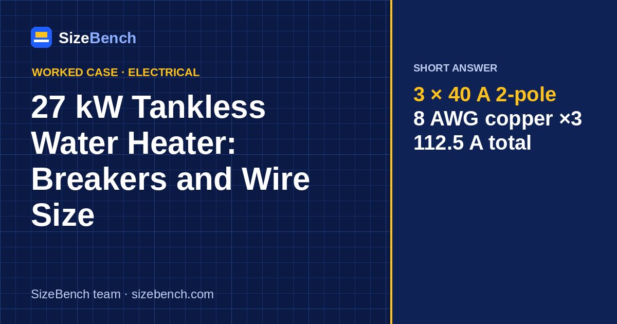
The case: a whole-house electric tankless water heater rated 27 kW at 240 V, built as three 9 kW heating chambers. The unit sits on a basement wall about 20 ft of cable from the main panel. The house has a 200 A service.
Short answer: three separate 40 A two-pole breakers, each feeding one chamber with 8 AWG copper (two hots plus ground; no neutral needed). Each circuit carries 37.5 A, the whole unit 112.5 A. That is the typical requirement printed in 27 kW manuals; yours rules if it differs.

1. Why three circuits instead of one
27 kW on a single 240 V circuit would be 112.5 A, which would need a large breaker and conductors too big for the heater's terminal block. Manufacturers split the load into 3 chambers of 9 kW, each wired as its own branch circuit:
I = 9,000 W ÷ 240 V = 37.5 A per chamber
The unit's control board stages the chambers on and off as the flow and inlet temperature change, so at a trickle only one may run; at full shower flow in winter all three run together.
2. Breaker size: 40 A or 50 A?
This is where tankless heaters confuse people:
- The NEC's rule that treats water heaters as continuous loads at 125% is written for storage-type heaters. A tankless unit is an instantaneous heater; its listing and installation instructions set the circuit.
- Most 27 kW units are listed for 40 A two-pole breakers per chamber, because 37.5 A fits under 40 A.
- If your inspector applies a 125% continuous treatment anyway, the design current becomes 46.9 A and the breaker goes to 50 A. 8 AWG copper at 75 °C (50 A) still works in conduit or with THHN, but NM-B would have to move to 6 AWG.
Ask before you buy wire; an inspector's reading of a local amendment is the one that counts.
3. Wire size per chamber
| Wiring method | Smallest copper for a 40 A breaker | Rating |
|---|---|---|
| THHN in conduit, 75 °C | 8 AWG | 50 A |
| NM-B cable, 60 °C | 8 AWG (8/2 with ground) | 40 A |
| 10 AWG, any method | not allowed | capped at 30 A |
Each chamber needs two hots and a ground; there is no 120 V load, so 8/2 NM-B with ground is enough. The three cables can share a stud bay, but bundling several current-carrying cables over long distances triggers ampacity adjustment; keep them separated through insulated spaces where you can.
4. Voltage drop
At 37.5 A per circuit, distance only matters on long runs:
| One-way length | Calculator pick at 3% | 8 AWG drop | 6 AWG drop |
|---|---|---|---|
| 10 ft | 8 AWG | 0.24% | 0.15% |
| 25 ft | 8 AWG | 0.60% | 0.38% |
| 50 ft | 8 AWG | 1.19% | 0.77% |
| 75 ft | 8 AWG | 1.79% | 1.15% |
| 100 ft | 8 AWG | 2.39% | 1.53% |
| 150 ft | 6 AWG | 3.58% | 2.30% |
Voltage drop matters more for a resistance heater than for a motor in one specific way: power falls with the square of the voltage. A 3% drop costs about 6% of heating power, which at full flow is a degree or two at the shower head. Keep the heater close to the panel when you can.
5. How many gallons per minute does 27 kW heat?
Heat delivered = 500 × gpm × temperature rise (°F), in BTU per hour, with 1 kW = 3,412 BTU/h. We assume 98% efficiency. Rearranged:
gpm = kW × 3,412 × 0.98 ÷ (500 × rise)
| Temperature rise | Typical situation | 27 kW | 18 kW | 36 kW |
|---|---|---|---|---|
| 35 °F | Warm southern inlet, 70 → 105 °F | 5.2 gpm | 3.4 gpm | 6.9 gpm |
| 50 °F | Mild inlet, 55 → 105 °F | 3.6 gpm | 2.4 gpm | 4.8 gpm |
| 65 °F | Cold inlet, 40 → 105 °F | 2.8 gpm | 1.9 gpm | 3.7 gpm |
| 77 °F | Very cold inlet, 35 → 112 °F | 2.3 gpm | 1.6 gpm | 3.1 gpm |
A typical low-flow shower head uses around 2 gpm. In a warm climate, 27 kW runs two showers at once; with a 40 °F winter inlet, it handles one shower plus a sink. That, and not the wiring, is the most common reason for disappointment with electric tankless heaters.

6. Can the service carry it?
The heater alone adds 112.5 A at 240 V. On a 200 A service that is more than half the capacity for one appliance, before the range, dryer, heat pump and EV charger. The NEC load calculation for the dwelling decides whether it fits. Practical notes:
- A 100 A service almost never supports a 27 kW unit.
- On a 200 A service with electric heat and an electric range, the calculation is often tight; a smaller unit or a heat pump water heater may be the better call.
- Some utilities restrict large instantaneous loads; ask before you buy.
7. On 208 V the heater is smaller
Apartment buildings often supply 208 V. Each element is a fixed resistance of about 6.4 Ω, so at 208 V it draws 32.5 A and the whole unit delivers only about 20.3 kW. Check the 208 V rating on the label before you count on the gallons-per-minute table above.
8. What happens to the old tank's circuit
The 50-gallon tank being replaced most likely has a single 4.5 kW element (upper and lower elements usually do not run together), which draws 18.8 A on a 30 A circuit with 10 AWG copper. That circuit cannot be reused for one of the tankless chambers: 10 AWG is capped at a 30 A breaker, and each chamber needs 40 A. Remove it or repurpose it for something that fits, and pull three new 8 AWG runs.
9. Energy: tankless versus a heat pump water heater
Wiring is a one-time job; energy is every day. Assume a household uses 60 gallons of hot water a day with a 65 °F rise. Heating that water takes:
60 gal × 8.34 lb/gal × 65 °F ÷ 3,412 ÷ 0.98 = 9.7 kWh per day
An electric tankless heater and an electric tank both turn electricity into heat at close to 100%, so they land near that figure; the tank adds some standby loss. A heat pump water heater with an assumed average efficiency factor of 3.0 would need about 3.2 kWh per day for the same water, and it typically runs on a 30 A or even a 120 V circuit. If the goal is lower energy use rather than endless hot water, compare both before committing to 112 A of new load.
10. Reading the label and manual
- Rated kW and voltage, often both 240 V and 208 V values.
- Number of circuits and the breaker size for each, plus the minimum copper size.
- Terminal range: some terminal blocks accept up to 6 AWG, some only 8 AWG. That matters if you upsize for distance.
- Minimum flow to activate, often well under 1 gpm. Very low-flow fixtures may not turn the heater on.
11. Installation checklist
- [ ] Three two-pole breakers sized per the manual, each labeled "WH chamber 1/2/3"
- [ ] Three runs of 8 AWG copper with ground (or as specified)
- [ ] Each circuit landed on its own terminal pair; no jumpers between chambers
- [ ] Equipment ground connected to the heater's ground lug
- [ ] Load calculation done for the service
- [ ] Water lines purged of air before the breakers are turned on, so elements never fire dry
12. Common mistakes
- One big breaker and jumpers inside the heater. Not allowed unless the manual offers that option.
- 10 AWG because "it's only 37 amps." 10 AWG copper is capped at a 30 A breaker.
- Energizing before filling. Dry-firing can destroy an element in seconds.
- Ignoring the service. A correctly wired heater on an overloaded service still trips the main.
Case summary
| Item | Result |
|---|---|
| Heater | 27 kW, 240 V, 3 × 9 kW chambers |
| Current | 37.5 A per chamber, 112.5 A total |
| Breakers | 3 × 40 A two-pole (per manual) |
| Wire | 3 × 8 AWG copper with ground |
| Flow at 65 °F rise | 2.8 gpm |
FAQ
What size breaker for a 27 kW tankless water heater? Typically three 40 A double-pole breakers, one per 9 kW chamber.
What wire size for a 27 kW tankless heater? 8 AWG copper for each of the three circuits, with ground. Each carries 37.5 A.
Do I need a 200 amp service? In practice, yes, and even then the load calculation must confirm it: the heater alone is 112.5 A.
Is 27 kW enough for two showers? At a 35 °F rise it delivers 5.2 gpm, enough for two. At a 65 °F winter rise it is 2.8 gpm, closer to one and a half.
Can I use aluminum wire for the chambers? Usually not. Most tankless terminal blocks are marked for copper only, and the manuals specify copper. Check the marking before considering it.
Check your own heater, distance or flow in the wire size and water heater calculators before ordering parts.
Try it with your own numbersWire Size Calculator→Sources and references
- NFPA 70, National Electrical Code (NEC) conductor ampacity by insulation temperature, small-conductor and continuous-load rules, requirement to follow listing and installation instructions
- U.S. Department of Energy – Tankless or demand-type water heaters how demand units heat water on flow and why flow rate limits them
- U.S. Department of Energy – Sizing a new water heater sizing a demand heater by flow rate and temperature rise
- SizeBench wire size calculator the ampacity and voltage-drop math used for each element circuit
- SizeBench water heater size calculator checking flow rate and temperature rise against household demand
Standards and data behind our calculators
How we made this guide
Every number in this guide is calculated by the same code as our calculators, from the standards listed above, and the page is tested before publication. The SizeBench team researched, wrote and reviewed it; we use automation and AI tools to help draft, never to produce the figures. Our methodology →
Revision history
- · Published